|
1. Purpose:
To test the performance of several homemade wireless antenna systems.

- Cantenna with USB dongle inside
- USB dongle
- Cantenna with built in antenna
- Biquad antenna
- Parabolic Dish antenna
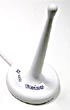
- WLAN omnidirectional indoor antenna
- Cylindrical parabolic reflector
- Access point: Wireless router with an Omnidirectional antenna, Omnidirectional
antennas always have vertical polarization.
2. Frequency spectrum and modulation methods:
| Frequency (MHz)* |
2412 |
2417 |
2422 |
2427 |
2432 |
2437 |
2442 |
2447 |
2452 |
2457 |
2462 |
2467 |
2472 |
| Channel* |
1 |
2 |
3 |
4 |
5 |
6 |
7 |
8 |
9 |
10 |
11 |
12 |
13 |
| |
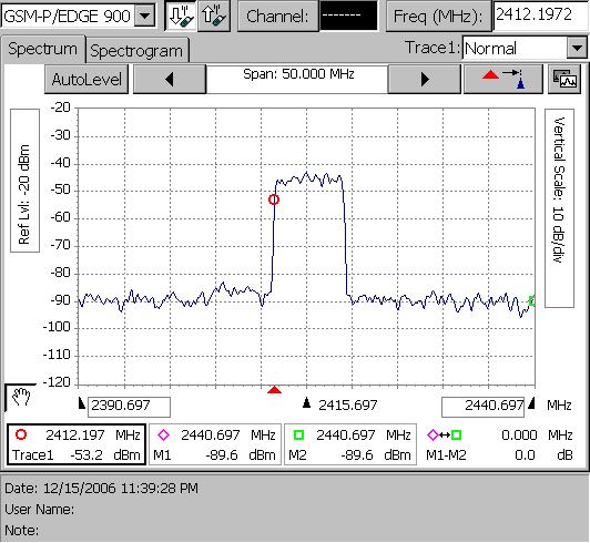
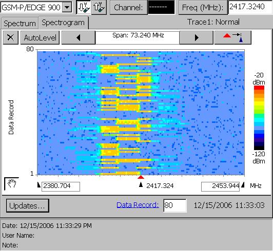
| Spectrum analyser measurement of wireless
communication between 2 computers: |
|
|
|
 |
* IEEE 802.11 documents, see below
- DBPSK modulation.
- DQPSK modulation
- OFDM modulation, 802.11g
Detected channels (Europ): channel 1 and 6
Transmited power of the transmitter (omnidirectional): 15 mWatt = 11.76 dBm,
a common value
3. Used materials:
| Belkin 802.11g wireless network card; chipset: BCM4306/BCM2050 |
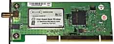 |
| Wireless router: Airvast |
 |
| Wireless router: Airvast, internal view |
 |
| WLAN omnidirectional indoor antenna |
 |
| EZ Connect g wireless SMC USB 2.0 dongle, SMC2862W-G |
 |
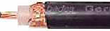
50 Ohm RG213 coax cable, Loss: 50/100m; (2.4GHz)
|
 |
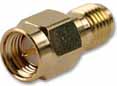
| RP SMA connector |
 |
| N plug connector, impedance: 50 Ω |
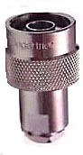 |
| N-type connector (crimp) male |
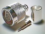 |
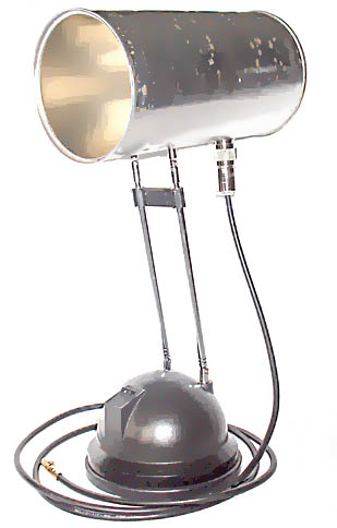
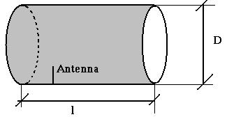
| Cantenna 1 Dimensions:
Diameter D: 100 mm
Length l: 183 mm
Built in antenna lenght: 31 mm
Antenna offset from the left: 45 mm |
 |

 |
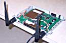
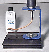
| Cantenna 2 with USB dongle inside
Dimensions:
Diameter D: 155 mm
Length l: 215 mm
Lenght USB dongle inside: 28 mm
Offset from the left: 35 mm
The effect of Horizontal or vertical placement of
the dongle: must be vertical as on the photo.
|
 |
 |
| Cylindrical parabolic reflector with
omnidirectional antenna Dimensions:
D: 330 mm
c: 120 mm |
 |
 |
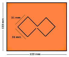
| Biquad antenna Dimensions:
Lenght of each side: 31 mm
Height from plate: 15 mm
Groundplane: 123mm/123mm |
 |
 |
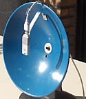
| Parabolic reflector with Biquad
antenna Antenna gain: 22 dB |
|
 |
| Parabolic antenna with USB Dongle |
|
 |
| MSI Bluetooth antenna |
|
 |
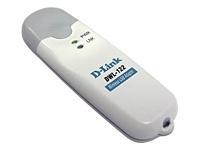
| Dlink USB antenna modification Model:
d-link dwl-122
Remove first the internal antenna.
Solder the external antenna.
Antenna taken from Wireless Airvast router
Antenna gain: 8 dB |
 |
 |
| Software: Network Stumbler 4.0;
GEOGEBRA |
|
4 Test environment:
Distance from Access point (Wireless Router as an Access Point) to the receiver: 45 meter, open air.
Used software: NetStumbler.
5. Measurement and calculation of
the coax cable impedance:
The characteristic impedance of a coax cable:
Zc = (138.log
(D/d)) / √Er,
where d is the diameter of the inner conductor and D is the diameter of the outer
conductor: Er: dielectric constant of the medium (if you don't know take 2.3)
a: inner conductor
b: Dielectric constant (Polyethylene: Er = 2.3)
c: outer conductor (Tinned copper braid)
d: Bonded aluminum foil
e: Jacket (Polyethylene)
Zc must be 50 Ω for all antennas, described
here
| Common Used Coaxial Cables: |
| Type |
Impedance (Ω) |
Attenuation 1 GHz (db/100m) |
| RG-213 A/U |
50 |
25 |
| RG-58 A/U |
50 |
50.8 / 900 MHz |
| RG-59 A/U |
75 |
39 |
6. Results:
|
DUT's (Measurement
1) |
Signal+ |
Noise |
SNR+ |
| Bluetooth
antenna, top |
-55 |
-100 |
45 |
| Bluetooth
antenna, front |
-66 |
-100 |
34 |
| Wlan antenna |
-72 |
-100 |
28 |
| Bluetooth
antenna with Cylindrical
parabolic reflector |
-60 |
-100 |
40 |
| Can dongle |
-56 |
-100 |
44 |
| USB dongle |
-75 |
-100 |
25 |
| Cylindrical
parabolic reflector (optimal position) |
-49 |
-100 |
51 |
| Cantenna |
-39 |
-100 |
61 |
| Cylindrical
parabolic reflector new |
-49 |
-100 |
51 |
|
DUT's (Measurement
2) |
Signal+ |
Noise |
SNR+ |
| Biquad antenna |
-37 |
-100 |
63 |
| Wlan antenna |
-61 |
-100 |
39 |
| Bluetooth
antenna |
-39 |
-100 |
61 |
| USB dongle |
-58 |
-100 |
42 |
| Can dongle |
-49 |
-100 |
51 |
| Cylindrical
parabolic reflector |
-37 |
-100 |
63 |
| Cantenna |
-39 |
-100 |
61 |
| Bluetooth
antenna with Cylindrical
parabolic reflector |
-37 |
-100 |
63 |
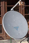
| Parabola dish with Biquad antenna |
|
|
|
| Parabola dish with Cantenna |
|
|
|
7. Comparison chart of the measurements:
Measurement 1:
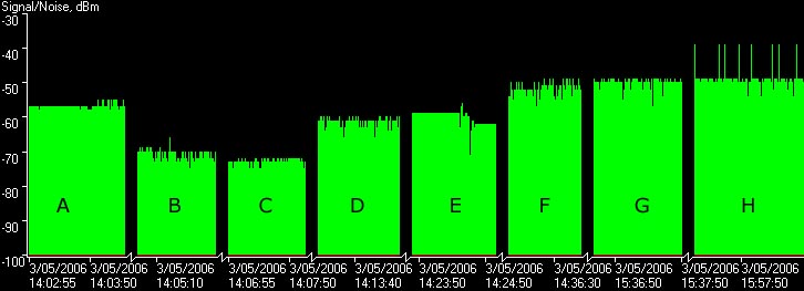
A: Bluetooth antenna at the top of the computer
B: Bluetooth antenna in front of the computer
C: Networkcard antenna
D: Bluetooth antenna in the focus point of the Cylindrical parabolic reflector
E: Candongle
F: Cylindrical parabolic reflector
G: Cantenna
H: Cylindrical parabolic reflector new construction
Measurement 2:
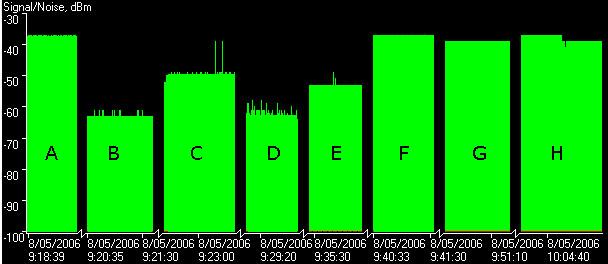
A: Biquad antenna
B: Networkcard antenna
C: Bluetooth antenna
D: USB dongle
E: Candongle
F: Cylindrical parabolic reflector
G: Cantenna
H: Cylindrical parabolic reflector with the bluetooth antenna
8. Some calculations
8.1 Power gain calculations:
dBm or dBmW is the
power measurement relative to 1 milliwatt,
dBm = 10 log P/P0;
when impedances are equal
3 dBm = 10 log P/P0
or P = 100.3.P0
or P = 2 P0
10 dBm = 10 log P/P0
or P = 101.P0
or P = 10 P0
or P = 10 mWatt
-50 dBm = 10 log P/P0
or P = 10-5.P0
or P = 0.00001 P0
or P = 10 nWatt

You can also use:
dBm/dBW/MilliWatts
Calculator
8.2 Power density from an isotropic antenna:
PD = Pt/4pd2
[Watts/m2]
Pt : transmitted power
d : distance from antenna
Remarks: - this value must be multiplied by the antenna gain G of the antenna (omni
directional antenna)
- dBi = dBd + 2.15
Remarks:
The signal strenght decreases by 6 dB when the distance doubles (outdoor),
indoor: 9 dB
8.3 Power density received by the antenna:
PR = PD.GR.l2/4p
[Watts]
GR.l2/4p
= effective area of the antenna
GR = gain of the receiving antenna
8.4 Friis Equation:
PR = Pt.GR.l2/(4pd)2
[Watts]
8.5 Wavelength calculations:
Wavelength l = c/f
c: speed of light: 3.108 m/s
Used Radio Frequency for WLAN, f = 2.4 GHz
The lenght of the internal antenna (cantenna) must be:
l/4
or 31 mm
The real used carrier frequencies are a little bit higher (see frequency table
above), for optimal results take 31 mm for antenna lenght.
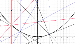
8.6 Parabolic Dish calculations:
Mathematical formula: y = a (x - p)2+ q
q = offset, take 0
p = horizontally displacement, take 0
New simplified formula: y = a (x)2 or y = x2/4f
where a= 1/4f ; use this equation to design your own parabola
The focus f of a given parabola = D2/16.c
D: Dish diameter
c: depth of the parabola antenna
Example of a Cylindrical parabolic reflector:
y = ax2 ; a = 0.05
y = 0.05x2
a = 1/(4f)
f = 1/(4a)
f= 5
Remark for a better result take a= 0.025
Calculation of the needed surface:
y = 0.05x2
Lenght = 2 0∫13
√(1 + ((0.05x2)')2) dx
Lenght = 0.2 0∫13
√(100 + x2) dx, to solve this
integral use the formule:
Using
the definite integral with a = 10, gives lenght = 44 cm
Result: we need a metallic surface with lenght = 44 cm, and height = 30 cm
8.7 Cantenna calculations:
Wavelenght: l = 3.108m/s
/ 2.4 GHz = 125 mm, in fact a little bit lower.
Built in antenna lenght: 31 mm = l
/ 4
Antenna offset from the left:
= 0.25l
/
√((1 -
(l/1.706D)2)
Lenght l of the cantenna must be > 0.75l
9. Useful online calculators:
CantennaCalc v0.2
Conversion from Watts
(W) to decibels "milliwatts" (dBm)
EIRP
Effective Isotropic Radiated Power calculator
Link Margin
Link Planning for Wireless LAN (WLAN)
RF Calculator
Conversion calculator from Watt to dBm and from dBm to Watt
Space loss calculator
Space loss calculator Km
10. Some practical calculations:
- Calculation of Free Space Loss =
FSL = 10 log (l
/4.p.d)2
= -100.4 dB for a distance of 1000 m -
Calculation of Maximum distance
FSL = PTR + GTR - PRC + GRC
-10 dB = 12 + 22 - (-80) + 10 - 20 = 104 dBm
PTR = Transmitted Power (12 dBm)
GTR = Antenna gain transmitter (22 dBi)
PRC = Receiver sensitivity (negative value)
(-80 dBm)
GRC = Antenna gain receiver
(10 dBi)
20 dB = Fade margin, dynamic RF parameters which
influences the signal - Maximum distance d: ==> (-104 dB) = 10 log (l
/4.p.d)2
==> dmax = 1500
m 11. Conclusions and remarks:
- Selfmade wireless cantenna is the best
for home applications.
-
The bigger the diameter of the cantenna, the
more access points you will detect at the
same time.
-
Selectivity is dependent of the diameter of
the cantenna.
-
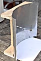
Antenna gain is much higher when you will
place the antenna in front of the computer
or placing a metallic shield behind the
receiver!!!
-
Glass does not effect the RF signal.
-
Humans indeed will cause a signal drop!!
- The USB can dongle is the best if you want
to detect more than one access point at the
same time
- Place your antenna as high as possible
- Take good care about your connectors, the
types listed above give the best results!!!!
12. Usefull links:
Antenna Measurements
Cisco Aironet Antenna Reference Guide
Geogebra
Hardware Comparison of some routers
Network Stumbler 4.0 a tool for Windows that allows you to detect Wireless
Local Area Networks (WLANs) using 802.11b, 802.11a and 802.11g. Use it for
finding locations with poor coverage in your WLAN or detecting other networks
that may be causing interference on your network.
RF Power Values
Wlan Antennas
13. Biographies/White papers:
IEEE
802.11b White Papers pdf file
IEEE
802.11g White Papers pdf file
IEEE 802.11 white paper
pdf file
802.11a Operates in the 5-GHz frequency range (5.125 to 5.85 GHz)
IEEE 802.16 WirelessMAN
IEEE 802.16 WirelessMAN Standard for Wireless Metropolitan Area Networks,
The IEEE 802.16 Working Group on Broadband Wireless Access Standards |